Introduction
Network topology visualization can be performed using a wide variety of technologies ranging from simple 2D applications to complex 3D applications. This approach utilizes the Unity (http://unity3d.com/) game engine to develop a network topology visualization in 3D complete with FPS controls in zero gravity and warp to zones.
Screenshots
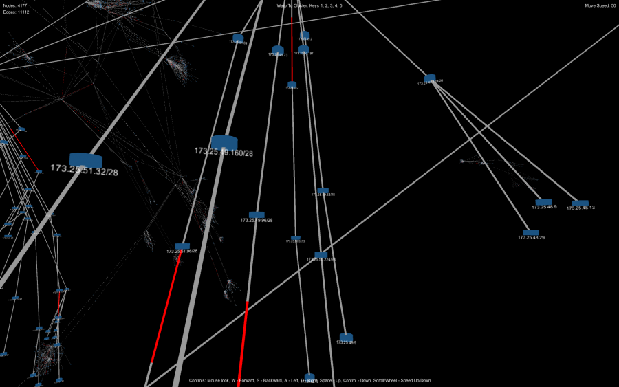
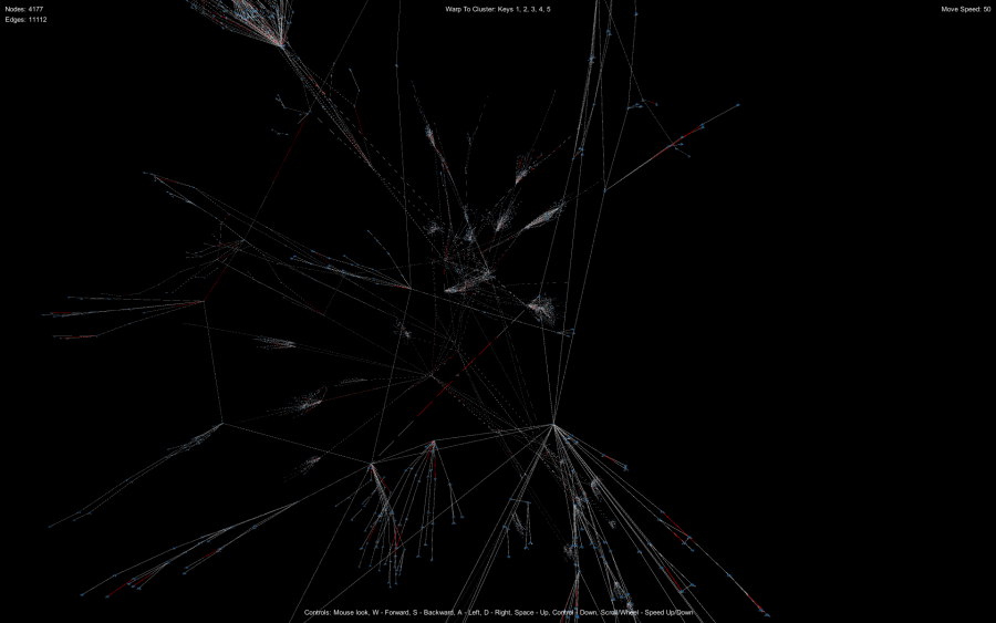
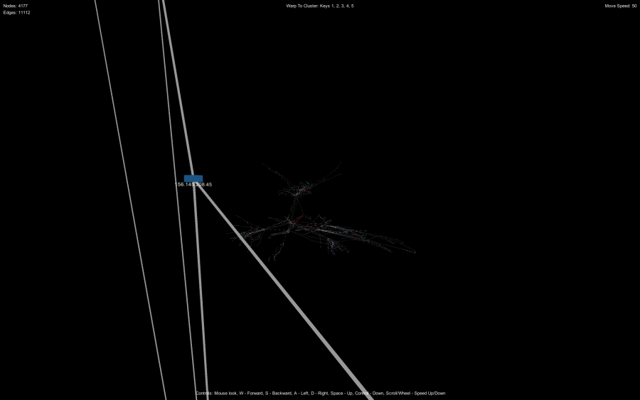
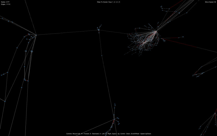
Source Files
The entire Unity project and source files are available for download: Download Unity Topology Source
Layout File Format
Let’s get started, first a data format (or formats) needs to be chosen for loading the layout or topology data. For my example I have chosen to use GraphML (http://graphml.graphdrawing.org/) being that Unity in C# directly supports XmlDocument.
The GraphML format I am using will support a collection of <node> and <edge> with standard and custom attributes:
1 | <node id="node_1" x="0" y="0" z="0" name="156.145.220.128/25" ... /> |
1 | <edge id="link_1" source="node_1" target="node_2" ... /> |
The node defines at the very least the node identifier which will uniquely identify the node in the topology map, the x, y and z which will become our Vector3 coordinates and the name attribute which will become the node label.
The edge defines at the very least the link identifier which will uniquely identify the link in the topology map, the source which identifies the source node of the link and the target which identifies the target node of the link.
Unity Setup
Next let’s define our basic Unity project structure. Under the Assets folder, create the following subfolders:
- Data
- Materials
- Prefabs
- Scenes
- Scripts
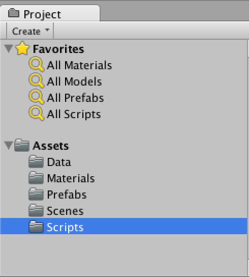
Once we have our basic folder structure setup, let’s create our 2 prefabs we will be using in our project, the Node prefab and the Link prefab.
The Node
Start by creating a new cylinder (GameObject -> Create Other -> Cylinder), size the cylinder down a little to make it look like and adding a Self-Illumin/Diffuse shader. I made mine blue, however feel free to choose whatever color you wish. Name the new object Node.
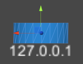
Next add a new script and call it Node (Node.cs). For the script we want to define a basic bit of logic to have our node text always facing the camera and a public string id:
1 2 3 4 5 6 7 8 9 10 11 12 13 14 15 16 17 | using UnityEngine;using System.Collections;namespace Topology { public class Node : MonoBehaviour { public string id; public TextMesh nodeText; void Update () { //node text always facing camera nodeText.transform.LookAt (Camera.main.transform); } }} |
Add a 3D Text object (GameObject -> Create Other -> 3D Text), move the 3D Text just below the cylinder and move the 3D Text as a child of the Node object. Next drag the reference into the Node Text (Text Mesh) property.
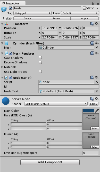
Finally drag the Node from the Hierarchy window to the Assets/Prefabs folder. Then remove the Node object from the Hierarchy view.
The Link
For the link, create an empty game object (GameObject -> Create Empty), name it Link and add a new script called Link (Link.cs). Within the script we’ll expose a few public properties such as id, source_id, target_id, etc; and define a LineRenderer which will be used to draw the line connecting the nodes.
1 2 3 4 5 6 7 8 9 10 11 12 13 14 15 16 17 18 19 20 21 22 23 24 25 26 27 28 29 30 31 32 33 34 35 36 37 38 39 40 41 42 43 44 45 46 47 48 49 50 | using UnityEngine;using System.Collections;namespace Topology { public class Link : MonoBehaviour { public string id; public Node source; public Node target; public string sourceId; public string targetId; public string status; public bool loaded = false; private LineRenderer lineRenderer; void Start () { lineRenderer = gameObject.AddComponent<LineRenderer>(); //color link according to status Color c; if (status == "Up") c = Color.gray; else c = Color.red; c.a = 0.5f; //draw line lineRenderer.material = new Material (Shader.Find("Self-Illumin/Diffuse")); lineRenderer.material.SetColor ("_Color", c); lineRenderer.SetWidth(0.3f, 0.3f); lineRenderer.SetVertexCount(2); lineRenderer.SetPosition(0, new Vector3(0,0,0)); lineRenderer.SetPosition(1, new Vector3(1,0,0)); } void Update () { if(source && target && !loaded){ //draw links as full duplex, half in each direction Vector3 m = (target.transform.position - source.transform.position)/2 + source.transform.position; lineRenderer.SetPosition(0, source.transform.position); lineRenderer.SetPosition(1, m); loaded = true; } } }} |
Being that this script was a bit larger, I’ll walk through what it does. First, the public properties; the id is the link identifier (ie. link_1), the source will become the source node reference, the target will become the target node, the sourceId will hold the id of the source node until the source property is populated and the same goes for the targetId. The status will hold a value of either Up or Down and will be used to color the LineRenderer. Within the Start() function, we create a new LineRenderer and color it according to the status property value setting its initial line positions to vectors (0,0,0) and (1,0,0) respectively. The Update() method waits until the source and target properties are populated then sets the LineRenderer end points. The loaded property makes sure this only happens once.
Finally drag the Link object from the Hierarchy window to the Assets/Prefabs folder. Then remove the Link object from the Hierarchy window.
Controller
Add a new empty game object (GameObject -> Create Empty) and name it GameController. Create a new script called GameController (GameController.cs). This script will be responsible for loading the layout file, creating Nodes and Links and handling general UI updates.
using UnityEngine;
using System.Collections;
using System.Xml;
using System.IO;

namespace Topology {

    public class GameController : MonoBehaviour {

        public Node nodePrefab;
        public Link linkPrefab;

        private Hashtable nodes;
        private Hashtable links;
        private GUIText statusText;
        private int nodeCount = 0;
        private int linkCount = 0;
        private GUIText nodeCountText;
        private GUIText linkCountText;

        //Method for loading the GraphML layout file
        private IEnumerator LoadLayout(){

            string sourceFile = Application.dataPath + "/Data/layout.xml";
            statusText.text = "Loading file: " + sourceFile;

            //determine which platform to load for
            string xml = null;
            if(Application.isWebPlayer){
                WWW www = new WWW (sourceFile);
                yield return www;
                xml = www.text;
            }
            else{
                StreamReader sr = new StreamReader(sourceFile);
                xml = sr.ReadToEnd();
                sr.Close();
            }

            XmlDocument xmlDoc = new XmlDocument();
            xmlDoc.LoadXml(xml);

            statusText.text = "Loading Topology";

            int scale = 2;

            XmlElement root = xmlDoc.FirstChild as XmlElement;
            for(int i=0; i<root.ChildNodes.Count; i++){
                XmlElement xmlGraph = root.ChildNodes[i] as XmlElement;

                for(int j=0; j<xmlGraph.ChildNodes.Count; j++){
                    XmlElement xmlNode = xmlGraph.ChildNodes[j] as XmlElement;

                    //create nodes
                    if(xmlNode.Name == "node"){
                        float x = float.Parse(xmlNode.Attributes["x"].Value)/scale;
                        float y = float.Parse (xmlNode.Attributes["y"].Value)/scale;
                        float z = float.Parse(xmlNode.Attributes["z"].Value)/scale;

                        Node nodeObject = Instantiate(nodePrefab, new Vector3(x,y,z), Quaternion.identity) as Node;
                        nodeObject.nodeText.text = xmlNode.Attributes["name"].Value;

                        nodeObject.id = xmlNode.Attributes["id"].Value;
                        nodes.Add(nodeObject.id, nodeObject);

                        statusText.text = "Loading Topology: Node " + nodeObject.id;
                        nodeCount++;
                        nodeCountText.text = "Nodes: " + nodeCount;
                    }

                    //create links
                    if(xmlNode.Name == "edge"){
                        Link linkObject = Instantiate(linkPrefab, new Vector3(0,0,0), Quaternion.identity) as Link;
                        linkObject.id = xmlNode.Attributes["id"].Value;
                        linkObject.sourceId = xmlNode.Attributes["source"].Value;
                        linkObject.targetId = xmlNode.Attributes["target"].Value;
                        linkObject.status = xmlNode.Attributes["status"].Value;
                        links.Add(linkObject.id, linkObject);

                        statusText.text = "Loading Topology: Edge " + linkObject.id;
                        linkCount++;
                        linkCountText.text = "Edges: " + linkCount;
                    }

                    //every 100 cycles return control to unity
                    if(j % 100 == 0)
                        yield return true;
                }
            }

            //map node edges
            MapLinkNodes();

            statusText.text = "";
        }

        //Method for mapping links to nodes
        private void MapLinkNodes(){
            foreach(string key in links.Keys){
                Link link = links[key] as Link;
                link.source = nodes[link.sourceId] as Node;
                link.target = nodes[link.targetId] as Node;
            }
        }

        void Start () {
            nodes = new Hashtable();
            links = new Hashtable();

            //initial stats
            nodeCountText = GameObject.Find("NodeCount").guiText;
            nodeCountText.text = "Nodes: 0";
            linkCountText = GameObject.Find("LinkCount").guiText;
            linkCountText.text = "Edges: 0";
            statusText = GameObject.Find("StatusText").guiText;
            statusText.text = "";

            StartCoroutine( LoadLayout() );
        }

    }

}
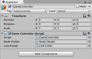
So now time for the walk through. The 2 public properties nodePrefab and linkPrefab define the prefabs to be used when creating nodes and links. The 2 Hastables, nodes and links define the collection which will hold the live instances of the prefabs Node and Link. The GUIText objects will reference the loading status displayed on the screen, the count of nodes and the count of links. The nodeCount and linkCount hold the actual numeric values for the count of nodes and links. The LoadLayout() method handles the loading of the GraphML file, it loads the xml file into a string, populates an XmlDocument object and iterates over the <node/> and <edge/> elements. When a <node /> is encountered we instantiate a Node object and populate its members and same goes for <edge /> with respect to populating a Link. Once all the Node and Link objects have been created, the source and target members of the Link object are replaced with the living references of Node through the call to MapLinkNodes(). The Start() method instantiates the nodes and links Hastables, resets the GUIText objects and starts a coroutine call to LoadLayout() which allows for returning control back to the Unity platform and preventing UI lock up.
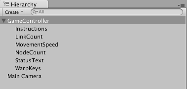
Next, lets’ add the GUIText objects. Create a GUIText object for LinkCount, NodeCount and StatusText at a minimum. Next place the GUIText objects in the Game view to their relative positions.
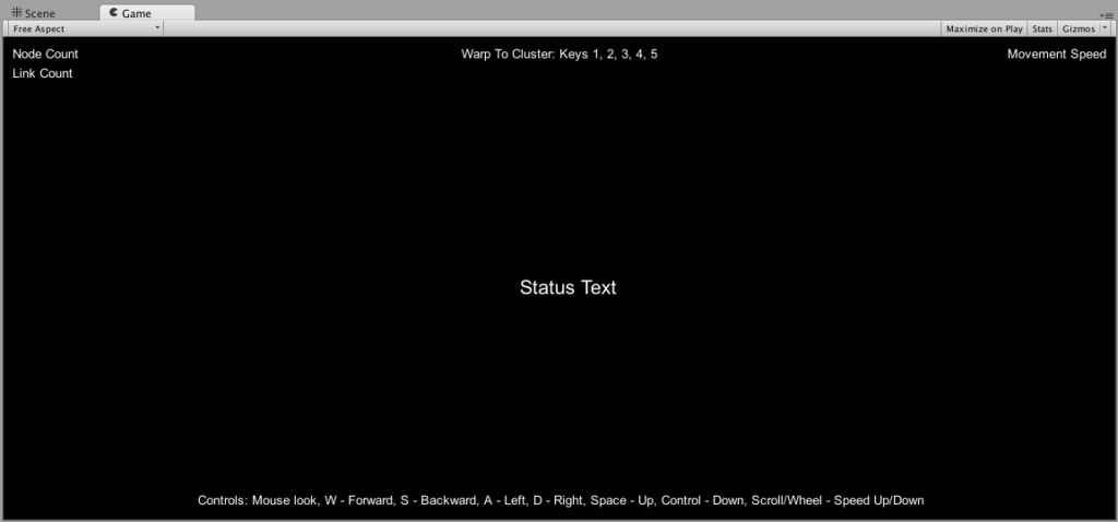
Make these GUIText objects a child of GameController and add drag the references to the GameController script references.
Camera
Click on the Main Camera object and add a new script CameraController (CameraController.cs). In this script we’ll add basic controls for WASD, Control, Space and Wheel/Scroll controls.
1 2 3 4 5 6 7 8 9 10 11 12 13 14 15 16 17 18 19 20 21 22 23 24 25 26 27 28 29 30 31 32 33 34 35 36 37 38 39 40 41 42 43 44 45 46 47 48 49 50 51 52 53 54 55 56 57 58 59 60 61 62 63 64 65 66 | using UnityEngine;using System.Collections;[AddComponentMenu("Camera-Control/Move ZeroG")]public class CameraControlZeroG : MonoBehaviour { public float speed = 5f; public GUIText movementSpeed; private Vector3 move = new Vector3(); private Vector3 cluster1 = new Vector3(1960, 1791, 2726); private Vector3 cluster2 = new Vector3(2042, 1579, 4254); private Vector3 cluster3 = new Vector3(2692, 81, 2526); private Vector3 cluster4 = new Vector3(531, 2317, 3776); private Vector3 cluster5 = new Vector3(-587, 2043, 2194); void Start(){ //set to first cluster position transform.position = cluster1; } void Update () { move.x = Input.GetAxis("Horizontal") * speed * Time.deltaTime; move.z = Input.GetAxis("Vertical") * speed * Time.deltaTime; move.y = 0; if (Input.GetKey ("space")) { move.y = speed * Time.deltaTime; } if (Input.GetKey ("left ctrl")) { move.y = -speed * Time.deltaTime; } //adjust speed with mouse wheel speed += Input.GetAxis("Mouse ScrollWheel"); if (speed < 5) speed = 5; movementSpeed.text = "Move Speed: " + speed; move = transform.TransformDirection(move); transform.position += move; //set warp to cluster controls if(Input.GetKey("1")){ transform.position = cluster1; } if(Input.GetKey("2")){ transform.position = cluster2; } if(Input.GetKey("3")){ transform.position = cluster3; } if(Input.GetKey("4")){ transform.position = cluster4; } if(Input.GetKey("5")){ transform.position = cluster5; } }} |
Walking through the above code, we define 2 public properties, speed which will hold the speed of movement through the zero gravity environment and GUIText movementSpeed which displays our current movement speed. Next we define a Vector3 for move which will be used as the movement vector. The following cluster[1-5] members define areas of the Topology which we’ll allow the camera to quickly jump to, feel free to replace these with your own coordinates. The Start() function places our camera at the first cluster position (the largest cluster). The Update() function first updates the move vector to move the camera in a direction. The space check will change our y movement upward. The left ctrl changes our y movement downward. The Mouse ScrollWheel changes our overall movement speed, then we display the speed in the GUIText. The final modifications are made to the camera’s transform position. The GetKey() calls for 1 through 5 warp our camera to the cluster[1-5] positions.
We’ll also want to import a standard asset from the Unity “Character Controller” set. Click Assets -> Import Package -> Character Controller, deselect everything, then online select “MouseLook.cs”.
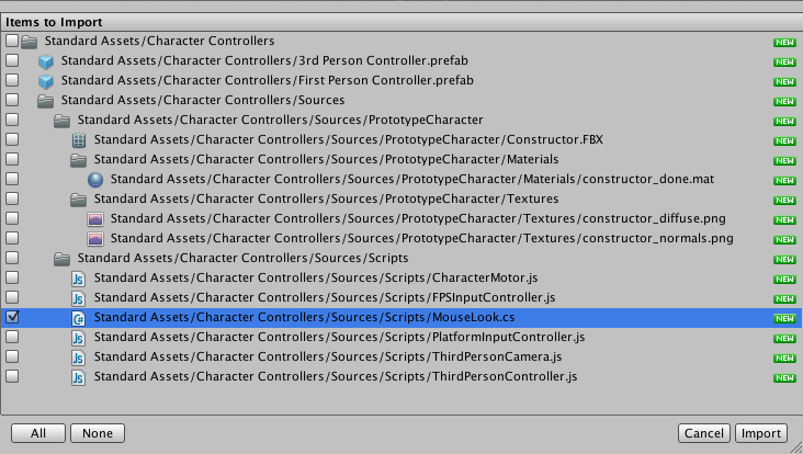
This will import the MouseLook.cs script which we’ll need to add to the Main Camera (Add Component -> Camera-Control -> Mouse Look).
Putting It All Together
Lastly, build, deploy and check it out. One thing to keep in mind is that the layout.xml in the Data directory (/Assets/Data/layout.xml) does not get deployed with the build. You will need to manually copy this file out to your build/deploy directory. Hopefully you won’t have any errors and will be able to view the 3D topology in all of its beauty and splendor. Have fun!


30 Comments
tom · March 17, 2014 at 4:17 pm
I really like this idea. But for some reason the unity web player doesn’t work for me. Could you update this article with a screen shot?
godlikemouse · March 17, 2014 at 4:45 pm
Bummer, I wonder why. I’ll add some screenshots as soon as I get a moment.
Ben · June 11, 2014 at 8:30 am
Hi Jason – this is cool. Can you clarify the relationship between this prj you’ve done and the Unity graph project at UbietyLab Inc.? The latter has a scripting environment that works with the Unity plugin, allowing me to feed in graphs (or other things) by pointing the engine to a file. Your approach above requires a compiliation and Unity developer (C#) tools, correct? Can your work interwork with the Web plugin?.. thanks.
godlikemouse · June 11, 2014 at 9:09 am
Hi Ben, I’ve never used UbietyLab, however the project I put together allows you to also pass in graph data as well as gives you full access to the source. This project also works with the Unity Web Plugin as the demo should illustrate.
marco · July 25, 2014 at 1:53 am
Wonderful solution. I was wondering how you generate your node coordinates. There are some layout algorithms available but did you use any 3D layout library? If so, could you please elaborate on how you achieved the node layout in 3d?
godlikemouse · July 25, 2014 at 9:01 am
Hi Marco,
I just threw a little something together for the 3D layout algorithm based on a standard force directed algorithm but modified for 3D. I have the algorithm publicly available if you’d like to check it out. I wrote a command line force directed layout utility that works in both 2D and 3D, it’s available at: https://github.com/godlikemouse/ForceDirectedLayout
marco · July 28, 2014 at 11:56 pm
Thank you, it is very helpfull.
Matt Gilliam · January 26, 2015 at 6:29 am
With the Unity 4.6 update they removed the 3D Text object so the current way of handling the id does not display anything. Do you know of a way to handle this in the current version?
godlikemouse · January 26, 2015 at 12:25 pm
Hi Matt, I think you’ll have to use either a TextMesh object, or generate UI Text and dynamically place them relative to the UI screen coordinates.
Frede · March 28, 2015 at 3:35 am
Such a big help – and especially thanks for refrencing your force directed layout algorithm
Sergio · October 19, 2015 at 11:48 am
Hi Ben,
Is the force directed layout system you use related to edge bundling approaches of the same name? Have you any pointers in implementing edge bundling in unity graph visualisations?
Thanks in advance,
Sergio.
godlikemouse · October 21, 2015 at 9:10 am
Hi Sergio,
I just wanted to verify that you intended this message to go to Ben and not me (Jason Graves, author of this post).
Sergio · October 27, 2015 at 12:21 pm
Hi Jason,
As explained in PM got crossed wires in posting.
I’ve been looking at force directed edge bundling algorithms, I’m guessing you were generating the clusters by similar means, any info on unity implementations would be great…
Thanks and sorry for the confusion.
Sergio
godlikemouse · October 27, 2015 at 12:55 pm
Hi Sergio,
I have an open source force directed algorithm you can port if you’d like to Unity. It’s located here: https://github.com/godlikemouse/ForceDirectedLayout
Hopefully that will help with what you’re looking for. If not, I’m sure there are plenty of other ones out there that might already be C# or JavaScript.
Sergio · October 27, 2015 at 1:03 pm
Thanks, I will definitely look at it asap, I’d seen the link below, and think it will be very handy to generate the node clusters. Since the edges need to be drawn in app, I will need something that will work at runtime! Porting the technique might be a possibility…
GIanluca · May 3, 2016 at 2:31 am
Hi, it’s a really nice project and i’m into it. I’m trying to use your topology with different data, but i can’t find a schema xsd (i’ve already searched in graphml website) or anything to use with excel for create a xml compatible with this project, because i always have a “not normalized” error. How can i solve and what are your dataset source (or how you created it), is it there any other instrument to create a xml data file with the “layout” caratheristics?
godlikemouse · May 3, 2016 at 8:49 pm
Hi Glanluca,
The XML file was generated directly from the results of a database populated with topology information. You may want to write a translation layer from whatever data source you’re using to generate the GraphML. Also, here’s the schema for GML: http://graphml.graphdrawing.org/specification/schema_element.xsd.htm
Hope this helps.
Grace · August 24, 2016 at 11:34 pm
HI,
HOw can i change the color of nodes based on a acondition??
godlikemouse · October 9, 2016 at 1:16 pm
Hi Grace,
Sorry for the late reply, for some reason I didn’t receive a notification for this comment. The way I do it is to change the shader itself to control the color. Have a look at: https://docs.unity3d.com/ScriptReference/Material.SetColor.html
Grace · August 24, 2016 at 11:35 pm
HI,
HOw can i chewnge the color of nodes???
Patrick Burns · August 29, 2016 at 6:43 pm
Thanks for the awesome writeup. This really filled in a bunch of gaps in my unity knowledge. I was able to grok most of the basics in a day thanks to this simple project. Keep up the good work!
godlikemouse · October 9, 2016 at 1:14 pm
Awesome! Glad it helped
Mark Grob · October 27, 2016 at 6:11 pm
Great work… perfect for what I am looking for.
godlikemouse · November 8, 2016 at 4:35 pm
Awesome! Glad to hear it. Thanks.
Raya · November 14, 2022 at 11:44 am
After 8 years people are still finding your tutorial. Hopefully this comment also still reaches you:). I followed all your steps (except for the GUI and movement one’s) but somehow can’t get it working since none of the nodes and links get instanced.
The error I’m receiving is : NullReferenceException: Object reference not set to an instance of an object Topology.GameController.Start () (at Assets/Scripts/GameController.cs:112)
As an alternative, I tried your project files from the ZIP but similar outcome (instead here I get 999+ error messages of object reference not set to an instance of an object). Any idea on how to resolve?
godlikemouse · November 14, 2022 at 12:44 pm
Hi Raya. It’s amazing that people are still referencing this. It’s very possible that the object properties of Unity have changed since the original publish date of this tutorial. You may need to set a breakpoint within the GameController.Start() method and step through each call to see what exactly is breaking. My guess is that either the instantiation method has changed within the Unity engine itself, or something along the lines of object assignment is failing. I’ll try install Unity and try this again if I get some free time. Please let me know if you make any progress or find any further details as to what the issue may be.
Raya · November 15, 2022 at 1:13 pm
Hi godlikemouse. Coincidentally managed to solve it today. In fact I needed to create the StatusText, nodeCount and linkCount text objects. I didn’t create them initially as I had already built the UI as part of a game I’m developing. Silly mistake;).
One thing that has changed from your instructions is that GUIText does no longer function. I’ve solved it as following:
in GameController.cs add using UnityEngine.UI
use private Text StatusText
private text NodeCountText
private Text linkCountText
Then later:
nodeCountText = GameObject.Find(“NodeCount”).GetComponent();
and same for LinkCount and StatusText
See https://forum.unity.com/threads/error-cs0619-guitext-is-obsolete-guitext-has-been-removed-use-ui-text-instead.826746/
godlikemouse · November 18, 2022 at 6:19 pm
Awesome, I’m glad you figured it out. Thank you for the follow up as well.
Calculating Warp Coordinates in Cyberspace | Cyber Situational Awareness · September 24, 2017 at 8:37 am
[…] would like to acknowledge and thank Jason Graves, Futurist, Experimentalist, Student of the Universe, for his excellent work on visualizing […]
STRING VisualizeR Network Node Analysis in VR – An Examination of STRING DB, Built in Unity and Experienced in the HTC Vive – Aviar Technology · November 18, 2020 at 6:41 pm
[…] which is itself built on Unity3D Network Visualization Tutorial from Jason Graves (https://collaboradev.com/2014/03/12/visualizing-3d-network-topologies-using-unity/). Both demonstrations are obtained via GNU GPL v 3 “copyleft” […]